Paul W. Marino Gages, Inc.
PWM Measurements & Standards (coming soon)
1 SE Ocean Blvd., Stuart FL 34994 USA
Phone/Text: 313.300.0134 email pwminc@pmargage.com


KOBA-step® Gage Bar, more

Length Measurement Uncertainty Plot
For the purposes of graphic analysis, the differences Delta L = La - Lr which are found and plotted, with the correct signs, for the individual measured lengths and runs in a length measurement uncertainty grid (figure 4). The top and bottom boundary lines produce a funnel shaped outline with the neck of the funnel measuring 2A (A = figure specified by manufacturer for length measurement uncertainty irrespective of length). 95% of all the test measurements must lie within or on the boundaries. A quantitative analysis is made simply by counting the number of measurements which lie outside the boundary lines.

Gage Face Position Plot
It is also possible to test the positions Lp of the gage faces as distances from the datum face with the Step-gage. If the relevant length errors Delta Lp given by position measurement in line with VDI guideline 2617 Part 3 are entered in a plot, then it is possible to see both the position of the test length and also the sequence, if for example the measurement points in a run are connected by straight lines. With a set of individual gage blocks this is not possible because they do not have any true common reference point and are not situated on a measurement line.
For analysis, use is made of a gage face position grid (figure 5) (similar to the length measurement uncertainty grid). The outline is symmetrical and similar in shape to a butterfly with a width across the waist of 1A. The parameters in this case correspond to the appropriate figures A1, K1, B1 and so on. As this grid is moved along the measured length L, at least 95% of all the measurements must always lie within or on the boundary lines, meaning that all the measurement points must do so consistently whatever the position of the waist. This ensures that any pairing of two gage faces (even from different runs) in the form of outside, inside or face-to-face dimensions will also lie inside the funnel of the length measurement uncertainty grid. Thus, the grid forms a combined graphic expression of both the equations given above for all points of measurement.
Comparisons Between the Test Standards "Gage Blocks" and "Step Gages"
Apart from the step-gage, parallel gage blocks are the reference standards known for the greatest accuracy of length. Gage blocks, however, are relatively flexible and have to be mounted at the AIRY points (symmetrical spacing a = 0.57735 x L) so that they are free of bending moments if this parallelism of the gage faces is to be maintained. The gage blocks for the individual test lengths can be individually placed one behind the other for shorter lengths and next to one another for longer lengths. When this is done, however, there is no way of obtaining the different gage points along a line of measurement which are desireable for measurement purposes.
Special Features and Advantages of the KOBA-step Gage
The step gage has a castellated configuration and contains a large number of forward and backward facing gage faces lined up along a single line of measurement. This line of measurement is the same for measurements between any faces and the position of the workpiece, that is to say the orientation of the carrying body, only has to be determined once to find this line. There are numerous possible combinations in various positions along the measurement line; the actual number of different interface dimensions for a step gage with 26 castellations (i.e., KOBA-step with a nominal size of 1020mm) is 1326.
A special feature of the KOBA-step step gage is the fact that the actual gage points are situated on the neutral fiber of the carrying body; this means that there are no first-order changes in length if the state of bending changes.
The configuration of the carrying body and the fact that the line of measurement is situated on the neutral fiber prevents any increase in the distance between the gage faces at the points where the carrying body is supported and prevents them from moving closer together at intervening points. In the KOBA-step step gage, which is neutral in bending, cylindrical gage blocks are fixed in position individually in an internal longitudinal groove formed in a rugged steel 55 x 55mm carrying body. The axis of the gage blocks is situated on the fiber of the carrying body which is neutral in bending and they form a series of castellations. The arrangement which has been adopted provides excellent protection for the gage faces. The strength of the carrying body, and the fact that the lengths do not vary if there are changes in the bending to which it is subject, mean that the KOBA-step step gage can be mounted in a wide variety of fashions, e.g., cantilevered with "zero position" support or with support at the Besselpoints.
Accessories
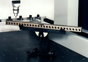
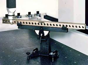
The range of accessories available which are needed for use with the step gage, such as swivel support and base allows the gage body to be mounted on the coordinate measuring machine in such a way as to be free of torsion. A support of this kind produces a particularly stable connection between the step gage and the table of the coordinate measuring machine (figures 7, 9 and 10).
The combination of the step gage and its accessories produces a complete system for making an overall check on the coordinate measuring machine. One particularly important point is that the procedure of checking the coordinate measuring machine can be carried out fully automatically under computer control.

Figure 7, KOBA-step aligned horizontally along the x-y plane diangonal, approximately 500mm above the table, stylus probe vertical. Shown with base and swivel support accessories.

Figure 9, KOBA-step aligned horizontally along the x-y diagonal plane, turned 90°, stylus probe horizontal, contact through cross-drills. Shown with base and swivel support accessories.

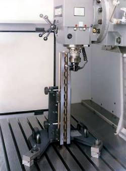
Figure 10, KOBA-step aligned vertically along the z-axis, standing in base, stylus probe horizontal.
Traceability
Since the acceptance or refusal of a coordinate measuring machine may depend on the outcome of the length measurement uncertainty test, it is advisable to always use officially calibrated testing equipment in order to avoid unpleasant surprises and incorrect interpretations. The KOBA-step step gage is available with optional DAkkS calibration-certificate and an additional (optional) co-efficient of thermal expansion (CTE) calibration.
The length measurement uncertainties which can currently be achieved with the step gage are:
If CTE is NOT calibrated: U = 0.08µm + 0.30 x 10^-6 x L
If CTE IS calibrated: U = 0.08µm = 0.25 x 10^-6 x L
DAkkS calibration of CTE: U = 0.04 x 10(-6) K_-1 + 0.007 x α + (0.03 x 10^-6 K_-1 m) / L
L is the Length and α the denomination of the coefficient in 10^-6 K_-1
Recalibration
As is normal with all measurement standards, the KOBA-step step gage should be recalibrated after a certain period. We recommend the following recalibration intervals: first calibration after one to two years and successive recalibration after two to three years.
Alignment of the KOBA-step
To define the position and orientation of the KOBA-step respective to the measuring line within the measuring volume, we recommend proceeding as follows:
As the carrying body with the fixed cylindrical gage blocks has been designed symmetrically to both sides, one of the external side surfaces and the upper external surface at the end of the large U-groove can be used for alignment.
Any points which are as large as possible can be sensed at either the side surface or at the upper external surface. Both planes so defined are squared off mathematically. A parallel line 27.5mm to the side surface and 30mm to the upper surface is the measurement line situated on the neutral fiber.
It is also possible to use both ends of the 7 x 10mm interior groove for the alignment and proceed in a similar way as before. The distance from the wall of the groove and the floor of the groove to the line of measurement is 5mm in both directions.
Practical Use

Figure 12, KOBA-step aligned vertically for checking height gages.

Figure 11, KOBA-step vertically oriented along the z-axis, standing in the base, stylus probe horizontal (not shown).
Practical experience using the KOBA-step step gage for checking the accuracy of coordinate measuring machines and accessing and interpreting the results has demonstrated the usefulness and potentially high information yield of the "length measurement uncertainty" method. The advantage lies in the fact that the measurement is carried out at precision gage faces using the normal gaging procedure and, in the main, the manufacturer's standard processing software. Since the unidirectional and bi-directional gaging of the inside and outside dimensions, dimensions between similarly oriented surfaces and successive dimensions from a given point occur even in the routine measurement of work pieces and since the measurements which have been obtained can be correllated with one another as desired, even after the event, it is a good idea to make full use of the opportunities offered by the step gage. What is more, a series of measurements at all the gage faces in succession provides a large amount of interrelated information and requires only a short time for measurement.
Since the length measurement uncertainty characteristic depends very much on the geometry of the coordinate measuring machine, the lines along which measurements are made should be as follows:
-
3 to 4 measurement lines which are diagonal in three dimensions (i.e., along the diagonals of an inscribed cube - at a gradient of approximately 35° - or along the diagonals of the cuboid representing the measured space).
-
2 diagonal lines of measurement in each coordinate plane (i.e., along the diagonals of a square - at a gradient of 45° - or the diagonals of a rectangle).
-
At least one line of measurement parallel to each coordinate axis.
At least 18 suitable lines of measurement have to be selected in order to arrive at a complete definition of the 18 geometrical cuboid characteristics of the entire measurement volume.
It must be stressed that reliable measurement results for a complex system cannot be achieved unless the stylus probes are included. Checking the coordinate measuring machine without mechanical contact, i.e., without using a probe, will not result in a comprehensive statement about the accuracy of the measuring machine.
Conducting Formal Acceptance Procedures and Monitoring the Precision of Machine Tools and Robotic Dimensional Gaging Systems.
The KOBA-step step gage can be used for checking the positioning accuracies of machine tools and articulated-arm robotic dimensional gaging systems, applications where it offers the same elegant approach and speed as when checking coordinate measuring machines. The accessory swivel support and base (described below) are required for this application.

Fig. 13, KOBA-step with swivel support and base, illustrated at various angular inclincations (stylus probe is not shown)

Fig. 14, KOBA-step with swivel support and base Size 1 for accommodating 1020mm length step-gage (stylus probe is not shown)
Regular use of the KOBA-step for monitoring dimensional gaging precision of machine tools is essential to total quality assurance. Total quality assurance demands more than mere precision dimensional gaging of finished work and components; regularly monitoring the dimensional gaging precisions of the macine tools employed in their fabrication is indespensible. Finished products must be machined to within precscribed dimensional tolerances if they are to pass final acceptance checks. Regular monitoring of machine tool dimensional gaging precisions provides valuable information on the degrees to which work/component dimensional tolerances are being maintained in machining operations.

Figure 15, KOBA-step installed on a swivel support and base, shown here spanning the major diagonal of the workspace of a vertical milling machine equipped with a dimensional gaging head.

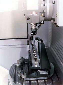
Figure 16, Koba-step shown horizontally aligned along the x-axis of the rotary bed of a machine tool equipped with a dimensional gaging head.

Figure 17, KOBA-step shown aligned vertically for checking the z-axis of a machine tool equipped with a dimensional gaging head.

Figure 18, KOBA-step shown installed on a flexible machining center for verifying its positioning accuracy (the center's dimensional gaging head is integrated into its tool chuck).
Applicable SIC Codes: 3423, 3545, 5049, 5084
Applicable NAICS Codes: 332212, 333515, 423490, 423830